PRODUCTS
-
EVA01a: One Stop Solution BYD Atto 3 EVA01b: One Stop Solution BYD E5 EVA01c:One Stop Solution BYD Dolphin EVA01d: One Stop Solution-Customized EVB01 - Powertrains System EVB02 - Energy Management EVB04B - Intelligent Power Battery EVB05B - BMS Training Bench EVB06 - Vacuum Pump Brake EVB07 - Drive Control System EVB09 - Battery Energy Recovery EVB10 - Charging Training Bench EVB11 - Drive System Connection EVB14 - Drive System Disassembly EVC01 - Drive System Disassembly EVC02 - Drive System Components EVC03 - Drive Motor Cutaway EVC04 - Gearbox & Axle Cutaway EVC05 - Battery Cutaway Model
-
CL-EP-001: Panoramic perception car CL-EP-002:Panoramic perception panel CL-EP-003: Millimeter Wave Radar Kit CL-EP-004: Vision Perception Kit CL-EP-005: Lidar Portable Kit CL-EP-006:Combined Positioning Kit CL-EP-007: Ultrasonic Sensors Kit CL-EP-008:Automotive Electronics Kit CL-EP-009:Millimeter Wave Radar Stand CL-EP-010: Vision Perception Stand CL-EP-011: LiDAR Training Stand CL-EP-012: Inertial Navigation Stand CL-EP-013: Ultrasonic Snesors Stand CL-DC-001: Chassis Bench CL-DC-002: Brake Integration Stand CL-DC-003: Steering Technology Stand CL-IC-001: Algorithm & Simulation CL-IC-002: Smart Cockpit Stand CL-IC-003: ADAS Assisted Driving Stand CL-IC-004: Parallel Cockpit and Remote Driving Vehicle Kit CL-IT-001: Connected Training Microcar CL-IT-002:Connected Logistics Microcar CL-IT-003:Sightseeing Mini Bus CL-IT-004:Car Basic Development CL-IT-005: Car Advanced Development CL-IT-006:Sightseeing Cart CL-IT-007: Roaming Cart CL-IT-008: Training Microcar-Educar CL-VC-001: Miniature Vehicle CL-VC-002: Miniature Vehicle Parallel Driving System CL-VC-003: Vehicle-Road Cooperation Sandbox and Cloud Control Platform CL-VC-004: V2X Vehicle-Road Cooperation
-
CL-A01 Gasoline Engine System Trainer CL-A02 Engine with Automatic Gearbox CL-A03 Engine with Air Conditining CL-A05 Engine Disassembly Trainer CL-A06 Engine Cutaway Stand Trainer CL-A07 Ignition System Panel Trainer CL-A08 Startup System Panel Trainer CL-A09 Charging System Panel Trainer CL-A10 Fuel Injection System Trainer CL-A17 Engine Parts & Components CL-B01 Automatic Transmission Trainer CL-B02Automatic Gearbox Disassembly CL-B03 Automatic Gearbox Cutaway CL-B04 Manual Gearbox Disassembly CL-B05 Manual Transmission Cutaway CL-B06 CVT System Trainer CL-B07 CVT Disassembly Trainer CL-C01 Clutch Stand Trainer CL-C02 Clutch Parts & Components CL-D01 Powertrains Cutaway Stand (FR) CL-D02 Powertrains Cutaway Stand (FF) CL-D03 Differentials, Axles, Drum CL-D04 Differentials Section Model CL-E01 Hydraulic Braking Trainer CL-E02 Pneumatic Braking Trainer CL-E03 Anti-Lock Brake System CL-E04 Braking Parts & Components CL-F01 Power Steering & Suspension CL-F02 Electric Power Steering Trainer CL-F03 Steering & Suspension Parts CL-G01 Chassis System Trainer CL-H01 Vehicle Cutaway Stand Trainer CL-I01 Automatic AC System (Cool) CL-I02 Automatic AC Trainer (H & C) CL-I03 Manual AC Trainer (Cool Only) CL-I04 Manual AC System Trainer (H&C) CL-I05 Air-Conditioning Component CL-I06 CAN-BUS Panel Trainer CL-I07 Air Bag and Seat Belt Panel CL-I08 Electrical / Electronics Stand CL-I09 Electrical / Electronics Panel CL-I10 Single Display Driving Simulator
E-mail:sales@coolifegroup.com
Phone:15814041681
Tel:15814041681
Add:Block 3,Wujiyungu,Rongxing Road,Xinci Street,Pingshan District, Shenzhen, China.
Category:CL-IT-006:Sightseeing Cart
CL-IT-006: Autonomous Sightseeing Vehicle "City Lights"I.Introduction to the Autonomous Sightseeing Vehicle TechnologyThis autonomous sightseeing vehicle represents the latest application of···
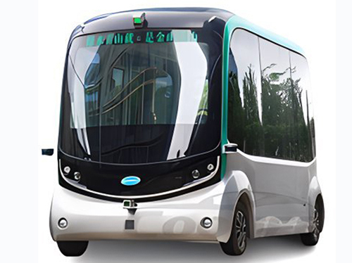
CL-IT-006: Autonomous Sightseeing Vehicle "City Lights"

I. Introduction to the Autonomous Sightseeing Vehicle Technology
This autonomous sightseeing vehicle represents the latest application of autonomous driving technology in the high-end tourism travel sector. The design integrates modern and fashionable elements, displaying a high sense of technology while ensuring a good viewing experience. Developed based on the drive-by-wire chassis technology of new energy vehicles, it is capable of driving on public roads and is equipped with a highly stable and reliable autonomous driving system, aimed at solving the last-mile problem in urban travel. Moreover, the vehicle adopts a shared travel mode and pure electric technology, reflecting the dual advantages of economy and environmental protection.
I. Detailed Explanation of Equipment Functions
1. Autonomous Driving System Based on Advanced Drive-by-Wire Technology:
The autonomous sightseeing vehicle employs mature drive-by-wire technology as its core control system, equipped with a fully automatic driving system, demonstrating professional application in the field of intelligent connected shuttle vehicles. This technology not only enhances the vehicle's safety and reliability but also showcases the cutting-edge autonomous driving technology to users through physical teaching methods.
1. High-Performance Drive-by-Wire Chassis:
The vehicle's drive-by-wire chassis uses mass-produced drive-by-wire VCU (Vehicle Control Unit) control, providing outstanding drive-by-wire performance. It achieves industry-leading levels in key indicators such as control precision, error management, response speed, and feedback accuracy, ensuring the efficient operation of the autonomous sightseeing vehicle under various road conditions.
2. Self-Developed Autonomous Driving Software:
The vehicle is equipped with a full set of self-developed autonomous driving software, integrating various sensors such as cameras, lidar, Ultrasonic Sensors, and GPS/IMU, providing comprehensive environmental perception capabilities. With advanced perception algorithms and obstacle behavior prediction, combined with laser and RTK positioning technology, the vehicle can accurately identify and avoid obstacles, optimize route planning, and thus achieve safe and efficient autonomous driving in mixed traffic conditions.
3. Customized Planning and Control Algorithms:
The autonomous sightseeing vehicle supports customized planning and control algorithms for mixed traffic conditions, capable of completing a range of advanced autonomous driving functions, including active tracking, obstacle recognition, active braking, station docking, and local path planning. The implementation of these advanced features makes the autonomous sightseeing vehicle not only suitable for tourist sightseeing but also applicable to various scenarios such as urban public transport, demonstrating the broad applicability of autonomous driving technology in modern transportation.
II. Detailed Equipment Specifications
1. Technical Specifications of the Autonomous Sightseeing Vehicle
1) Vehicle Type and Drive Configuration
A. Vehicle Positioning: Drive-by-wire sightseeing minibus.
B. Drive Method: Rear-mounted, rear-wheel drive, ensuring good power transmission and driving stability.
C. Steering System: Front-wheel steering, providing flexible handling performance.
D. Body Construction: Non-load bearing design, optimizing vehicle weight distribution and structural strength.
1) Size and Performance
A. Curb Weight: 2100kg, lightweight design enhances energy efficiency.
B. Maximum Gross Weight: 3290kg, securing the load capacity for passengers and luggage.
C. Passenger Configuration: Maximum number of passengers is 14, with 8 seats (including a safety officer's seat), meeting the needs of small group travel.
D. Body Dimensions: Length 4500mm × Width 2000mm × Height 2635mm, spacious cabin space provides a comfortable riding experience. E. Wheelbase: 3300mm, ensuring driving stability. F. Track: Front and rear tracks are both 1760mm, maintaining good vehicle balance.
2) Performance Indicators
A. Maximum Speed: 30km/h, suitable for city sightseeing and low-speed driving environments.
B. Endurance: 160km (steady speed method-20km/h), meeting daily operational needs.
C. Climbing Capability: Maximum gradient of 15%, easily handling complex terrains.
3) Energy and Battery
A. Energy Storage System: Uses lithium iron phosphate batteries, environmentally friendly and safe. B. Battery Capacity: 105Ah, supporting long-term operations without frequent charging.
4. Advanced Computing and Sensor Configuration
1) Computing Unit
A. CPU Configuration: 6 cores and 12 threads, with a main frequency of 4.1G, equipped with 12M third-level cache, powerful processing capability.
B. GPU Configuration: Independent image processor, with 3584 CUDA processors, memory frequency of 15Gbps, and memory capacity of 12G DDR6, supporting complex image processing tasks.
C. Memory and Storage: 16GB LPDDR4x2666MHz memory, 500GB solid-state drive, ensuring data processing and storage needs.
D. Interface: Provides gigabit Ethernet + WiFi connection, USB 3.0 interface, supporting various peripheral connections.
4) Perception and Positioning
A. Front-view Cameras: Dual Sensor IMX291, 1/2.8" lenses, USB 3.0 interface, 2 million pixels, supporting up to 1920*1080p 50 frames video stream, capable of recognizing vehicles, pedestrians, traffic signs, and traffic lights.
B. Lidar: Four 16-line lidars with a wavelength of 905nm, maximum ranging distance of 150m, and accuracy of ±2cm, supporting a working temperature range of -30°C to +60°C, providing all-around environmental awareness。
C. Combined Positioning Unit: Supports RTK mode, GNSS single-point mode, triple-mode seven-frequency (GPS, BDS, GLONASS) positioning, built-in 6-axis IMU, ensuring precise positioning and stable navigation.
D. Ultrasonic Sensor: Covers a ranging distance of 130mm to 5000mm, high precision, supporting complex environmental short-range obstacle detection.
III. Platform Features
1. Complete Autonomous Driving System: The autonomous sightseeing vehicle is equipped with a comprehensive autonomous driving system capable of safe, autonomous navigation in various road conditions. The system supports L4-level autonomous driving functions, including but not limited to high-precision map-dependent navigation, active tracking, obstacle recognition, automatic braking, station docking, and local path planning.
2. Parameter Setting Controls: A user-friendly interface is provided, allowing operators to adjust the behavior strategies of the autonomous driving system based on specific needs, including speed settings, path priority, etc., ensuring vehicle operation complies with the requirements of specific scenarios.
3. High-Precision Map Generation: The vehicle is not only capable of utilizing existing high-precision maps for precise navigation but also has the capability to generate high-precision maps. By collecting environmental data and using specialized software for processing, detailed maps can be created for use in autonomous driving.
4. Sensor Teaching Software: Considering educational and R&D needs, the system offers specialized training software for various sensors, supporting step-by-step teaching to help learners better understand the principles and application scenarios of autonomous driving technologies.
5. Indoor and Outdoor Positioning Technology: By integrating various positioning technologies, the autonomous sightseeing vehicle can accurately track or drive based on high-precision maps in indoor and outdoor environments, enhancing its adaptability and flexibility in complex settings.
IV. Supporting Software
1. Vision Testing Software: This software integrates modules for vehicle and pedestrian recognition, lane detection, and traffic light status recognition, supporting rapid installation, calibration, and debugging of cameras. In addition, it includes functionalities for dataset collection and processing, model training, and comes with a comprehensive development package that includes Python3, TensorFlow, CUDA, and more, as well as machine learning DEMOs, providing users with a complete visual processing solution.
2. Millimeter-wave/Ultrasonic Sensor Testing Software: This software is specially designed for testing millimeter-wave and Ultrasonic Sensors, capable of receiving sensor data streams, displaying detection effects under different conditions, and reading fault information, facilitating system tuning and maintenance.
3. Lidar Testing Software: Provides interface testing, configuration (including Ethernet settings, time synchronization, motor parameter adjustments), and data stream reception with point cloud visualization capabilities, supporting in-depth understanding of lidar applications in autonomous driving systems.
4. Combined Navigation Testing Software: Software for testing and calibrating the combined navigation system, supporting calibration, navigation mode configuration, coordinate axis settings, and port data output configurations. By receiving combined navigation data, the software can effectively assist in system tuning and optimization.
- Prev:no more
- Next:no more